
Page 25 - DT 13-1 March 2023
P. 25
20-26-André Gaul-Q8_6-7-8-Ivoclar.qxd 3/27/2023 2:01 PM Page 4
prosthetic section 25
DENTAL TECHNOLOGY, JANUARY-MARCH 2023
We proceeded to print a set of tryins in KeyDenture Base resin at 100µm layer thickness. be noted that, at the earlier stage of the
Normally, 3D printed try-ins would be printed in a tooth shaded material of the same brand and process, the stone models had been
chemistry as the pink denture base, to which a pink composite could be applied to simulate gin- scanned “as-is”, without first blocking out
giva, but Keystone did not have this available at the time. In any case, our primary concern at any of the vestibular undercut below the
this stage was not so much the esthetics but rather the adaptation, function and correct posi- residual ridge. This resulted in the denture
tion of the teeth. The patient was fully aware that these were not the final dentures. flanges, filling in those undercuts.
We were soon astonished at how well these dentures fit. The patient was equally quick to In order to be able to properly fit the
comment on how comfortable and light they felt. Some design modifications were nonetheless denture bases over the printed models,
needed, namely the position of the medial line and the height of the occlusal plane. We there- some of the undercut, particularly on the
fore returned to Dentca Design and applied these minor adjustments. In retrospect, both Mr. Lin upper model, had to be burred down
and I agreed that, had we been a bit more diligent in taking initial patient measurements, we slightly (The same would have applied to
could easily have avoided the need for these adjustments. Fortunately, making adjustments in the stone models). In addition, the posteri-
Dentca Design is simple and a second and final set of denture files were generated in no time. or limits of the denture flanges themselves
This time, the prosthetic bases and teeth were printed separately and in their respective resin. would later have to be reduced slightly, as
While the bases were printed at 100µm, the tooth segments were printed at 50µm. Each print- is later explained, for patient comfort.
ed parts were thoroughly cleansed of any uncured resin and then dried. The teeth were then installed in the
The printed parts were then post-cured according to the resin manufacturer’s recommenda- bases, starting with the posterior seg-
tions. This is critical for several reasons: To achieve the final dimension of the parts, reach the ments, and bonded in place, using the
material’s optimal physical properties and to ensure the elimination of any residual monomer. same KeyDenture Base resin (Figures 14
After post curing, the support stubs were burred off of the parts (Figure 25). The teeth and and 15). To maximise the bond, the roots
denture bases were then ready for assembly. It could be argued that a 3D printed denture work- of the teeth were lightly roughened with a
flow eliminates the need to assess the occlusion and adaptation on a conventional articulator, bur.
since the contraction of dental acrylic and dimensional changes associated with it is no longer To cure the resin, an LED wand was
a variable, but 3D printed parts are subject to some dimensional changes and occlusal contact used, but this is merely to fix the teeth in
points can require some adjustments, in particular, during mandibular movements. Since this place (Figure 16). A final post-curing of
was our first attempt at 3D printed dentures, we preferred to weigh on the side of caution and the assembled dentures was done in an
so, went ahead with designing and printing special models with registration pins. Alternatively, LED curing unit to permanently bond the
the stone models could themselves have been mounted on an articulator and used in lieu of 3D teeth and to cure the layer of resin applied
printed models. to the surface of the bases. (Figure 19).
The alignment and occlusion of our printed models was validated with our patient’s wax rims The dentures were then returned to the
(Figure 13). The alignment and vertical dimension provided by the registration pins were spot models and the occlusal contact points
on and no adjustments were necessary. The printed denture bases were then mounted. It should were verified (Figure 20). Since we had
already tested the tryins in the patient’s
mouth, it was no surprise at this stage that
the contact points required little alter-
ations.
Final adjustments during lateral and
protrusive movements would be per-
formed in-mouth.
A preliminary polishing on the lathe
was done, using pumice and compound
(Figure 20). The dentures were then
ready for final fitting in-mouth (Figure
22). A slight reduction of the labial flange
on both the upper and lower dentures
were required for patient comfort and ease
of insertion. A final polishing was per-
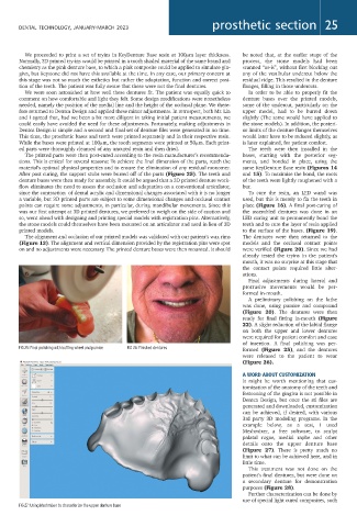
FIG 25: Final polishing with buffing wheel and pumice FIG 26: Finished dentures
formed (Figure 25), and the dentures
were released to the patient to wear
(Figure 26).
A WORD ABOUT CUSTOMIZATION
It might be worth mentioning that cus-
tomization of the anatomy of the teeth and
festooning of the gingiva is not possible in
Dentca Design, but once the stl files are
generated and downloaded, customization
can be achieved, if desired, with various
3rd party 3D modeling programs. In the
example below, as a test, I used
Meshmixer, a free software, to sculpt
palatal rugae, medial raphe and other
details onto the upper denture base
(Figure 27). There is pretty much no
limit to what can be achieved here, and in
little time.
This treatment was not done on the
patient’s final dentures, but were done on
a secondary denture for demonstration
purposes (Figure 28).
Further characterization can be done by
use of special light cured composites, such
FIG 27: Using Meshmixer to characterize the upper denture base