
Page 20 - DT 15-1
P. 20
10-21-Claudio_6-7-8-Ivoclar.qxd 01-05-2025 07:56 Page 11
20 prosthetic section DENTAL TECHNOLOGY, JANUARY-MARCH 2025
FIG 94: Cemented work in anterior view 81 FIG 95-96: Details of the locking, with and without the FIG 96
framework inserted in the oral cavity
FIG 97: Final control radiographic status FIG 98-99: Before and after images with peri-oral tissues FIG 99
ing impression using an individual tray for the fabrication of the
framework (Figure 79).
In the laboratory, customization continues with the coloring of zir-
conia. When particular esthetic needs arise, we perform a cut-back of
the vestibular surfaces and layer dedicated feldspathic ceramic
(Figure 80).
Next, the metal sheaths are glued into the prepared recesses, and
the OT Cap Micro attachments are screwed in (these are interchange-
able) (Figures 81 to 83).
Then, we fabricate the framework, preparing two hard wax blocks
with reference notches, while on the antagonist we apply a 0.5 mm
thermoformed sheet (Figures 84 and 85). The clinician conducts the
final test and registration using self-curing resin (Luxabite) to finalize
the work (Figure 86).
The position is checked on the working models and everything
matches perfectly, thanks to the transfer system described earlier
(Figure 87). We proceed with assembling the upper posterior teeth
FIG 100-101: Pictures before and after with intraoral tissues in composite on the framework, customizing and integrating them
with the previous reconstructions (Figure 88). Retention attach-
ments and Teflon inserts are then placed in dedicated containers to
provide the patient with a stable, yet removable prosthesis (Figure
89).
These images demonstrate that even using monolithic material, if
properly and carefully processed, can yield aesthetically pleasing
results (Figures 90 and 91).
From a functional perspective, however, there is no comparison to
conventional layering techniques. While we have long used verticula-
tors, wax duplications, and molding methods, we now find that mod-
eling in wax and transforming it into zirconia represents the most
ergonomic and predictable approach. Even the composite teeth on the
framework are customized using colored resins (Optiglaze, GC)
(Figures 92 and 93).
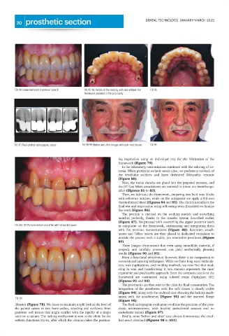
The prosthetics are then sent to the clinic for final cementation. The
integration of the prosthetics with the soft tissues is clearly visible
(Figure 94), along with the occlusal view showing the locking mech-
anism with the attachments (Figure 95) and the inserted flange
FIG 101
(Figure 96).
libraries (Figure 78). We chose to maintain a split lock at the level of The final radiographic evaluation confirms the precision of the pros-
the palatal suture in two hemi-arches, avoiding any resilience from thetic reconstructions, with healthy periodontal support and no
posterior soft tissues that might conflict with the rigidity of a single endodontic lesions (Figure 97).
anterior structure. The locking mechanism is sent to the clinic for the Finally, some "before and after" case photos demonstrate the excel-
esthetic-functional try-in, after which the clinician takes the position- lent result obtained (Figures 98 to 101).