
Page 18 - DT 15-1
P. 18
10-21-Claudio_6-7-8-Ivoclar.qxd 01-05-2025 07:56 Page 9
18 prosthetic section DENTAL TECHNOLOGY, JANUARY-MARCH 2025
Without this, we risk creating incongruent upper anatomical and In this way, the clinician can directly restore the optimum condition
morphological curves. that was designed in the laboratory (Figures 65 and 66). Moreover,
For the lower wax-up, we use another SAM articulator accessory in this specific case—compared to when reconstructing arches on nat-
that helps define the Occlusal Plane (Figure 44). ural teeth—there is no need to use specific techniques to create inter-
The inclination of this plate relative to the Frankfurt Plane deter- proximal separations for the passage of dental floss, as this is a pros-
mines the occlusal course, which varies by skeletal class. thesis.
In this case—a normotypic Class I—we set the inclination at 12° to After the time required for tissue healing following abutment prepa-
the Frankfurt Plane (Figure 45), a value derived from Prof. Slavicek’s ration, we proceed to the next phase. Since the prosthetic abutments
extensive case database of 5,500 records. judged maintainable do not require endodontic, restorative, or peri-
Alternatively, individualized occlusal planes can be determined via odontal therapy, we are ready to take the final impressions: one upper,
cephalometric analysis of a lateral teleradiograph. one of the provisional tested by the patient, and one of the antago-
Curves of Spee and Wilson are also considered. These may be gen- nist—all with precision materials (Figure 67).
erated using pre-made templates, but we prefer to design them indi- To preserve the vertical dimension of occlusion (DVO), the inter-
vidually using the linear plate as a reference (Figure 46). maxillary position and anterior guides are tested with the temporaries
The diagnostic wax-up is completed with the upper posterior assem- to perform the registration. We make use of the temporaries them-
bly (Figures 47 and 48), ensuring that the palatal cusps align per- selves and proceed with the following technique:
fectly within the fossae of the lower teeth (Figures 49 and 50). We disassemble one provisional hemi-arch while the other is left in
Given that the patient did not necessarily request a fixed upper pros- position, and we take the registration between the abutments and the
thesis—which would require complex and lengthy implant therapy— antagonist arch teeth (Figure 68).
and considering the presence of a removable prosthesis on tapered We then disassemble the other hemi-arch, leaving the registration
crowns in the lower arch, the proposed prosthetic plan is as follows: we just made in place, and record the relationship between the abut-
ments and the teeth on the opposite side (Figure 69).
UPPER ARCH In this way, we ensure that the laboratory receives the intermaxil-
• Monolithic zirconia blocking 1.3 to 2.4 with Rhein83 extra-coronal lary relationship in exactly the same position as the temporary in the
attachments. oral cavity.
• Framed with a palatine bar and composite teeth. In the laboratory, we articulate the upper model with the lower
model using the registration (Figure 70). What we observe is a per-
LOWER ARCH fect match between the registration taken in the oral cavity and the
• Reconstruction of anatomical ideal in molded composite on the position of the master models on the articulator (Figure 71).
existing teeth of the removable denture. We can then proceed with the execution of the final work using the
Then, once the shaping and transformation of the wax-up into resin information from the provisional, which—let us not forget—was
is carried out in acrylic for the fabrication of the temporary in the pre- checked by the clinician and tested by the patient for a period that may
liminary (Figures 51 and 52), we proceed with the resining of the vary from one to three months.
upper temporary with hooks. Consequently, we perform the control of By mounting the model of the temporaries, we can exactly repro-
the protrusive and lateral movements on the articulator (Figures 53 duce both esthetics and function, as validated in the functional mouth
to 55). At this point, it is of paramount importance that the clinician (Figures 72 and 73).
inserts the temporary and transfers the lower wax-up in exactly the In addition, through the incisal table, we can execute and verify the
same modality as they were made in the laboratory. guiding paths of centric, protrusive, and lateral movements, with the
For the correct placement of the fixed temporary, we prepare a rigid same inclination checked and tested on the patient (Figure 74).
silicone template (90 Shore) made on the original (unwaxed) antago- For those accustomed to functionalizing the temporaries, the infor-
nist model. This is stable and precise and is interposed between the mation gathered can be transferred directly to the definitive recon-
arches to lock the temporary in the position in which it was made on struction.
the articulator relative to the antagonist (Figures 56 and 57). This In this case, after waxing, we preferred to use the “Double Scan”
device allows the clinician to insert the provisional into the oral cavity technique, though it is also possible to use digital capture techniques
in exactly the same position as it was made in the laboratory—a step by matching the temporaries.
of paramount importance (Figures 58 and 59). Then, to allow the Through the technique we have used daily for years—processing
clinician to reconstruct the abutments in the oral cavity in a propor- pre-sintered zirconia (green phase)—we precisely define the transition
tionally correct manner, we prepare the model on which the predeter- lines, occlusal surfaces, emergence profiles, and surface textures
mination of the abutments was made (Figure 60) in a transparent (Figures 75 and 76). The sintering process is carried out with dedi-
template (Figure 61). cated programming, including conventional cooling times; we never
In this way, the clinician can print the reconstructions and finish perform rapid cooling.
them with burs to obtain optimal preparations (Figure 62) that also The restoration is adapted to the model and verified under a micro-
allow for targeted and minimal relining of the temporary in the prelim- scope to check marginal fit (Figure 77).
inary phase (Figure 59). Finally, on the lower wax-up, we design a For the choice of attachments, we opted for the OT Cap Micros with
clear template for the composite restoration of the lower arch (perma- Rhein83 bonding sleeves because they provided the best guarantee of
nent mock-up) on the existing prosthesis (Figures 63 and 64). support, accuracy, and reproducibility in zirconia using the appropriate
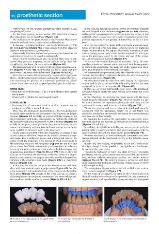
FIG 76: Details of the palatal area and of the support for the FIG 77: Multi-layer zirconia after the first firing of FIG 78: Structure ready for the aesthetic functional try-in
extra coronal attachment glazing/staining in the oral cavity