
Page 20 - Dental Technology 12-3
P. 20
20-22-Thomas Lee article-Q8_6-7-8-Ivoclar.qxd 10/6/2022 8:47 PM Page 1
20 prosthodontic section DENTAL TECHNOLOGY, JULY-SEPTEMBER 2022
THE ABCsOF OCCLUSION AND ARTICULATIONS
REDUCING POSITIVE ERRORS FOR LESS ADJUSTMENTS
THOMAS E. LEE
This article will focus on the ABCs (Axis, Bite, and Chewing) of
Occlusion and Articulation that can be easily implemented to create
restorations that require fewer adjustments, saving time and reduc-
ing stress. The initial step in reducing positive errors in articulation
begins with accurate impressions and bite records as any error in the
technique or material will create a high restoration.All philosophies
have the same objective of equal contacts of the occluded teeth with
no interferences in all movements. Laboratory technicians can
achieve this objective on whatever articulator they may use, yet most
restorations still need adjustments when placed in the patient’s
mouth because of inaccurate impressions and/or positive errors in
the Axis, Bite and Chewing.
An articulator is an instrument that represents the temporo-
mandibular joints (Axis) or jaws to which study casts may be attached
to simulate the static (Bite) and dynamic (Chewing) relationship
between the occlusal surfaces of the teeth during mandibular move-
ments. Positive errors occur when the articulator under compensates FIG 1
for mandibular movements, resulting in a positive feature on the
occlusal surface where that feature should be smaller or non exis-
tent.11 Positive Errors can create interferences that may need to be
adjusted in the Axis (opening and closing movements), the Bite and
Chewing (envelope of function movements) depending on the disclud-
ing factor of the protrusive pathway, influence of Bennett movement,
and steepness of the anterior guidance. Negative Errors occur when
the articulator overcompensates for mandibular movements, resulting
in a negative feature on the occlusal surface which allows the teeth to
disclude more freely. 11
AXIS
It is important to relate the teeth to the patient’s axis to simulate
more accurate axis movements in an articulator. The most common FIG 2 FIG 3
error in relating study models is using a simple hinge articulator
without the use of a facebow. The axis in simple hinge articulators
(Figure 1, redpoint B) are always located below the patient’s axis
(Figure 1, green point A).Therefore, simple hinge articulators pro-
duce more vertical opening and closing axis movements (Figure 1,
red pathway b) than the patient’s opening and closing axis move-
ments (Figure 1, green pathway a). This positive error in axis
movements can create interferences in the mesial inclines of the
upper teeth and/or distal inclines of the lower teeth that will require
adjustments. 1
Research shows that a facebow has a statistical average to the
axis by referencing the patient’s ears which relates the study models
2
much closer to the patient’s axis to reduce positive errors. The Kois
Dento-Facial Analyzer (DFA) is a simple instrument that incorpo-
rates a 3-Dimensional guide plane to reference how the occlusal
plane relates to the face for esthetics, as well as having a functional
relationship of the teeth to the axis based on an average axis-incisal
3
distance of 100mm (Figure 2). This 100mm axis-incisal distance
4
is supported by Monson’s Spherical Theory (4in=101.6mm) , FIG 4
5
Bonwill’s Equilateral Triangle , as well as other research showing
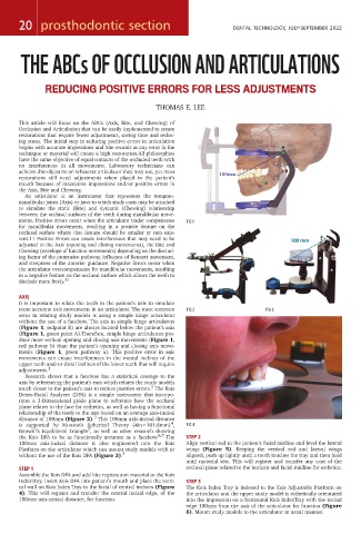
the Kois DFA to be as functionally accurate as a facebow. 6,7 The STEP 2
100mm axis-incisal distance is also engineered into the Kois Align vertical rod to the patient’s facial midline and level the lateral
Platform on the articulator which can mount study models with or wings (Figure 5). Keeping the vertical rod and lateral wings
without the use of the Kois DFA (Figure 3). 3 aligned, push up lightly until a tooth touches the tray and then hold
until material sets. This will register and transfer any cant of the
STEP 1 occlusal plane related to the horizon and facial midline for esthetics.
Assemble the Kois DFA and add bite registration material to the Kois
IndexTray. Insert Kois DFA into patient’s mouth and place the verti- STEP 3
cal wall on Kois Index Tray to the facial of central incisors (Figure The Kois Index Tray is indexed to the Kois Adjustable Platform on
4). This will register and transfer the central incisal edge, of the the articulator and the upper study model is esthetically orientated
100mm axis-incisal distance, for function. into the impression on a horizontal Kois IndexTray with the incisal
edge 100mm from the axis of the articulator for function (Figure
6). Mount study models to the articulator in usual manner.