
Page 25 - DT14-1
P. 25
24-27-KLINGNER article-Q8_6-7-8-Ivoclar.qxd 4/15/2024 8:37 PM Page 2
DENTAL TECHNOLOGY, JANUARY-MARCH 2024
prosthetic section 25
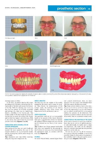
FIG 9: Choice of teeth FIG 10 FIG 11
FIG 12 FIG 10-13: Digital proof
FIG 15
FIG 14-15: The model is prepared by removing the undercuts, the median raphae is slightly covered and the extent of the denture base is marked. Subsequently, a first proposal for the base
of the prosthesis is obtained that is adapted with the "free forms"
chewing waxes in C-Plast. MODEL ANALYSIS and started SmileCreator. Here we have
In the office, the dentist lined up the ridges The first step was the analysis of the model, uploaded the two images and combined them
according to the CAM plan, determined the ver- required by the system and it cannot be avoid- with the scanned chewing wax model.
tical height of the bite and checked for fullness ed. Then follows the determination of the Tip: Make several reference lines in the chew-
of the lips. With the chewing wax in-situ we occlusal plane, the marking of the incisive ing wax to be able to combine it better! Now
also took two photos for M-Smile (extended papilla, tuberosity, ridge center, lowest and we had the opportunity to set up a full denture
and smiling). In a later step we digitally pro- largest point for the masticatory unit etc. and see what it would look like to the patient
duced a recording of the bearing pin. This without her presence in the laboratory. This
worked similar to the functional tray except for TOOTH SELECTION allowed us to better evaluate the form and size
the fact that we made the valleys a bit shorter The prosthetic teeth are set up automatically of the teeth. Then we returned to wizard mode.
and we built the support pin in between. With based on the analysis of the model. However,
it, the dentist then determined the horizontal that's just a suggestion that should be individu- CORRECTION OF THE POSITION OF THE TEETH
position of the bite (Figures 4 to 8). ally adapted. Different shapes and sizes of teeth At this point it should be noted how much fol-
can be selected on the basis of the circum- lows: since in the end we all mill the prosthet-
FABRICATION WITH CERAMILL FDS IN stances. ic teeth individually, we hardly have a single
IVOTION WORKFLOW Tip: we like to use a larger anterior teeth splint arch limitation. The teeth can be enlarged,
After getting all the data, we could finally get than what was suggested by the program as reduced, widened, shortened and the posterior
started! We have registered the case in the this fits better in most cases. Once having found quadrants can be split, etc.
Ceramill database. So, we scanned the models the appropriate teeth, we continue with the For the rest, the user has all the necessary
and the chewing wax, and we added images for next step (Figure 9). lines, planes and points available, to correct the
the M-Smile. assembly. Using the chain mode, the position of
Tip: Determine post dam before scanning; M-SMILE the individual teeth in the arch can be correct-
doing this step later complicates life. We exited Wizard Mode, entered Expert Mode ed quite easily (Figures 10 to 13).