
Page 11 - DT 15-1
P. 11
10-21-Claudio_6-7-8-Ivoclar.qxd 01-05-2025 07:55 Page 2
DENTAL TECHNOLOGY, JANUARY-MARCH 2025
prosthetic section 11
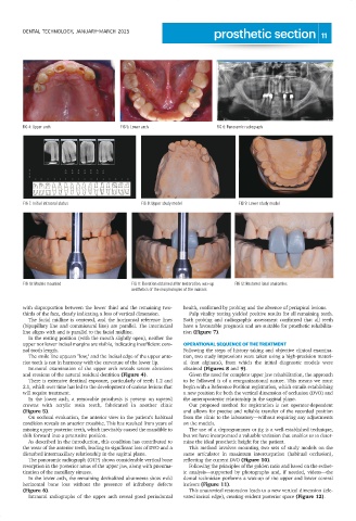
FIG 4: Upper arch FIG 5: Lower arch FIG 6: Panoramic radiograph
FIG 7: Initial intraoral status FIG 8: Upper study model FIG 9: Lower study model
FIG 10: Models mounted FIG 11: Elevation obtained after restoration, wax-up FIG 12: Restored ideal anatomies
aesthetics of the morphologies of the incisors
with disproportion between the lower third and the remaining two- health, confirmed by probing and the absence of periapical lesions.
thirds of the face, clearly indicating a loss of vertical dimension. Pulp vitality testing yielded positive results for all remaining teeth.
The facial midline is centered, and the horizontal reference lines Both probing and radiographic assessment confirmed that all teeth
(bipupillary line and commissural line) are parallel. The interincisal have a favourable prognosis and are suitable for prosthetic rehabilita-
line aligns with and is parallel to the facial midline. tion (Figure 7).
In the resting position (with the mouth slightly open), neither the
upper nor lower incisal margins are visible, indicating insufficient coro- OPERATIONAL SEQUENCE OF THE TREATMENT
nal tooth length. Following the steps of history taking and objective clinical examina-
The smile line appears "low," and the incisal edge of the upper ante- tion, two study impressions were taken using a high-precision materi-
rior teeth is not in harmony with the curvature of the lower lip. al (not alginate), from which the initial diagnostic models were
Intraoral examination of the upper arch reveals severe abrasions obtained (Figures 8 and 9).
and erosions of the natural residual dentition (Figure 4). Given the need for complete upper jaw rehabilitation, the approach
There is extensive dentinal exposure, particularly of teeth 1.2 and to be followed is of a reorganizational nature. This means we must
2.1, which over time has led to the development of carious lesions that begin with a Reference Position registration, which entails establishing
will require treatment. a new position for both the vertical dimension of occlusion (DVO) and
In the lower arch, a removable prosthesis is present on tapered the anteroposterior relationship in the sagittal plane.
crowns with acrylic resin teeth, fabricated in another clinic Our proposed method for registration is not operator-dependent
(Figure 5). and allows for precise and reliable transfer of the recorded position
On occlusal evaluation, the anterior view in the patient’s habitual from the clinic to the laboratory—without requiring any adjustments
condition reveals an anterior crossbite. This has resulted from years of on the models.
missing upper posterior teeth, which inevitably caused the mandible to The use of a deprogrammer or jig is a well-established technique,
shift forward into a protrusive position. but we have incorporated a valuable variation that enables us to deter-
As described in the introduction, this condition has contributed to mine the ideal prosthetic height for the patient.
the wear of the anterior teeth, leading to significant loss of DVO and a This method involves mounting two sets of study models on the
disturbed intermaxillary relationship in the sagittal plane. same articulator in maximum intercuspation (habitual occlusion),
The panoramic radiograph (OTP) shows considerable vertical bone reflecting the current DVO (Figure 10).
resorption in the posterior areas of the upper jaw, along with pneuma- Following the principles of the golden ratio and based on the esthet-
tization of the maxillary sinuses. ic analysis—supported by photographs and, if needed, videos—the
In the lower arch, the remaining devitalized abutments show mild dental technician performs a wax-up of the upper and lower central
horizontal bone loss without the presence of infrabony defects incisors (Figure 11).
(Figure 6). This anatomical restoration leads to a new vertical dimension (ele-
Intraoral radiographs of the upper arch reveal good periodontal vated incisal edge), creating evident posterior space (Figure 12).