
Page 13 - DT 15-1
P. 13
10-21-Claudio_6-7-8-Ivoclar.qxd 01-05-2025 07:55 Page 4
DENTAL TECHNOLOGY, JANUARY-MARCH 2025
prosthetic section 13
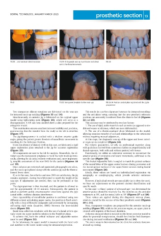
FIG 28: ... and maximum lateral excursion FIG 29-31: Diagnostic wax-up in protrusive and lateral FIG 30
centric functional movements
FIG 31 FIG 32: Transparent template for the mock-ups FIG 33-34: Position control plate registered with the jig/de-
programmer
Two transparent silicone templates are fabricated on the wax-ups This results in a perfect alignment between the intraoral recordings
for intraoral mock-up molding (Figures 13 and 14). and the articulator setup, ensuring that the new prosthetic reference
Simultaneously, an anterior jig is fabricated on the original upper positions are accurately transferred from the clinic to the lab (Figures
model using light-curing resin (Figure 16), which will serve as a 22 and 23).
deprogrammer. A 0.5 mm heat-molded sheet is also prepared for the This accuracy can be attributed to two key factors:
antagonist model. 1. The use of rigid, stable materials such as resins (as opposed to tra-
This combination ensures excellent intraoral stability and precision, ditional waxes or silicones, which are more deformable).
guaranteeing that the transfer from the study to the lab is error-free 2. The use of a thermo-stamped sheet fabricated on the model,
(Figure 17). allowing seamless transfer of occlusal relationships to the articulator
The jig/deprogrammer is crafted with a shallow anterior guide without requiring manual adjustment.
angle, giving the patient greater freedom of mandibular movement in At this stage, the diagnostic wax-up of the upper and lower anteri-
searching for the Reference Position. or segments is completed (Figure 24).
Given the absence of diatoric teeth in this case, we fabricated a rigid For esthetic parameters, we rely on professional expertise along
upper registration plate attached to the jig for accurate registration with guidelines derived from numerous studies on proportionality and
(Figure 15). dental exposure, both with and without perioral soft tissues.
All components are sent to the lab for analysis. Meanwhile, the cli- Functionally, we utilize an articulator accessory to reconstruct the
nician uses the transparent templates to mold the resin mock-up intra- anterior guides of protrusive and lateral movements, calibrated to the
orally, allowing for an initial esthetic evaluation and, more important- specific case (Figure 25).
ly, tangible assessment of the new DVO for the patient (Figures 18 This Incisal Adjustable Table is angled to match the palatal surfaces
and 19). of the mesial lobes of the upper central incisors during protrusion and
Once esthetics are reviewed and optimized, photographs are taken, the mesial-palatal surfaces of the upper/lower canines during lateral
and the mock-up is placed along with the anterior jig and the thermo- movements (Figure 26).
formed lower sheet. Ideally, these values are based on individualized registration via
If, as in this case, the esthetics and new DVO are satisfactory, the jig axiography or condylography, which provide articular eminence
remains unaltered—having been fabricated to match the height of the angles.
wax-ups. If adjustments are needed, they can be performed at this However, if individual records are unavailable (as is often the case),
point. we base our adjustments on the patient's skeletal classification and
The deprogrammer is then inserted, and the patient is allowed to specific needs.
rest for approximately 10–15 minutes. Subsequently, the patient is In this case—a Class I patient of advanced age—we determined the
asked to perform gentle anteroposterior excursions against the jig’s anterior guides should be relatively flat. We therefore set the articular
incisal table—without clinician interference. eminences at 30°, and the incisal table at 35° (Figures 27 and 28).
Once repeatability of mandibular position is confirmed using two These values are applied during this diagnostic wax-up phase,
different-colored articulating paper marks, the position is fixed anteri- which is crucial for the success of the final prosthetic result (Figures
orly with a drop of flowable composite and posteriorly by interposing 29 to 31).
self-curing rigid resin (Luxabite, DMG) between the heat-molded Next, transparent templates are prepared for the anterior mock-up
sheets (Figure 20). molding (Figure 32), while in the posterior region, an upper plate is
Facial data collection concludes with the use of a facial arch to spa- created with imprints of the lower dentition.
tially orient the upper model in relation to the Frankfurt plane. A thermo-stamped sheet is molded on the lower posterior model to
To achieve this, both the orbital indicator and adjustable nasion allow for potential re-registration, should the clinician find discrepan-
must be used (Figure 21). cies during intraoral verification (Figures 33 and 34).
In the laboratory, the upper model is mounted with the facial arch The entire setup is then returned to the clinic for aesthetic-function-
and matched to the lower model using the intraoral registration. al mock-up testing.