
Page 12 - DT Vol 15 No 3
P. 12
12 I implantology DENTAL TECHNOLOGY, JULY-SEPTEMBER 2025
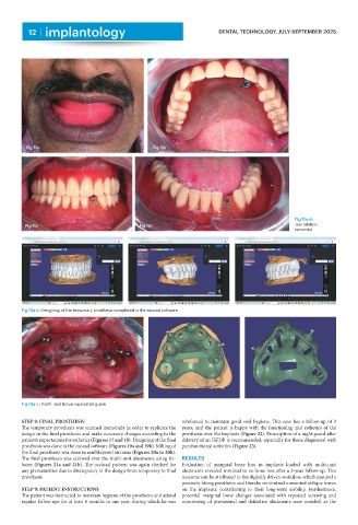
Fig 11a Fig 11b
Fig 11a-d:
Fig 11c Fig 11d Jaw relation
recorded
Fig 12a-c: Designing of the temporary prosthesis completed in the exocad software
Fig 13a-c: Tooth- and tissue-supported guide
STEP 8: FINAL PROSTHESIS reinforced to maintain good oral hygiene. This case has a follow-up of 3
The temporary prosthesis was scanned intraorally in order to replicate the years, and the patient is happy with the functioning and esthetics of the
design in the final prosthesis and make necessary changes according to the prosthesis over the implants (Figure 22). Prescription of a night guard after
patient’s expectations for esthetics (Figures 17 and 18). Designing of the final delivery of an ISFDP is recommended, especially for those diagnosed with
prosthesis was done in the exocad software (Figures 19a and 19b). Milling of parafunctional activities (Figure 23).
the final prosthesis was done in multilayered zirconia (Figures 20a to 20h).
The final prosthesis was screwed over the multi-unit abutments using tie- RESULTS
bases (Figures 21a and 21b). The occlusal pattern was again checked for Evaluation of marginal bone loss in implants loaded with multi-unit
any prematurities due to discrepancy in the design from temporary to final abutments revealed minimal to no bone loss after a 3-year follow-up. This
prosthesis. outcome can be attributed to the digitally driven workflow, which ensured a
passively fitting prosthesis and thereby minimized unwanted oblique forces
STEP 9: PATIENT INSTRUCTIONS on the implants, contributing to their long-term stability. Furthermore,
The patient was instructed to maintain hygiene of the prosthesis and attend potential marginal bone changes associated with repeated screwing and
regular follow-ups for at least 6 months to one year, during which he was unscrewing of provisional and definitive abutments were avoided, as the